Contact · Newsletter · DEUTSCH
To meet the requirements of future digital business processes, we have developed the IO/5640. It allows IGW/9xx gateways to be connected directly with process inputs and outputs.
Thus, control and data acquisition tasks can be realized with an IGW/9xx, e.g. in the field of telecontrol, condition monitoring or predictive maintenance.
An IO/5640 offers 8 analog inputs (each 4x 4-20 mA as well as 0-10 V), 6 digital outputs and 5 digital inputs for that.
IO/5640 and IGW/9xx are connected via RS485 and use the Modbus RTU protocol for communication, with the IO/5640 acting as a Modbus slave and the gateway as a Modbus master. A total of up to 15 IO/5640 can be operated as a cascade on a single IGW/9xx.
Of course, the IO/5640 can also be operated with an (industrial) PC, e.g. to make analog data available to an MES or ERP system.
The range of functions of the IO/5640 can be expanded by so-called Application-specific Code Functions (ACF) and adapted to individual requirements.
The ACF are special software components that enable e.g. sensor data fusion, time-critical data pre-processing, high-speed timing measurements and much more directly in the IO/5640. The results are stored in optional Modbus registers.
That way, two binary sensors can, for example, be used to start and stop two independent 16-bit timers in order to measure the time span of the travel distance of a linear drive with a resolution of 1 millisecond.
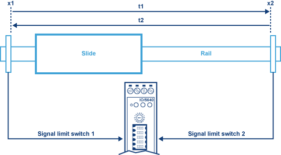
Figure 1: Measurement of the time span of the travel distance of a linear actuator
For example, to measure the time spans t1 and t2 of the distances x1 > x2 and x2 > x1 for the movements of an air-driven drive carriage with millisecond accuracy, the outputs of the binary proximity sensors (limit switches 1 and 2) are connected to two IO/5640 inputs. One limit switch starts the timer, the other one stops the time measurement. The values for t1 and t2 can be read via Modbus RTU.
The IO/5640 works as a signal acquisition unit for various analog sensor elements. The digitalized data is read out by an IGW/9xx gateway via Modbus RTU, converted into the application-related data formats (e.g. in CSV, JSON, XML) and supplemented by corresponding metadata if needed.
Sensor data fusions are also possible. Using various protocols, the CSV/JSON/XML data can then be forwarded to a cloud or other IT systems (e.g. MES, ERP, CRM, SQL database) or automation modules.

Figure 2: Example Industry 4.0 Sensor System
A PC-based measurement data acquisition system ( = DAQ system) is used to acquire physical process parameters (e.g. current, voltage, temperature). The IO/5640 module is responsible for signal conditioning and A/D conversion
From the PC, the digitalized data is read out by the DAQ software via Modbus RTU (usually, a Modbus driver is included in the scope of delivery of good DAQ systems) and processed further. For location-independent visualization (e.g. smartphone app, SCADA), the PC forwards the data to a cloud if required.
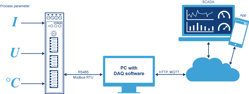
Figure 3: Example PC-based DAQ System
The IO/5640-DS is a special variation of the IO/5640 (see Product variations and accessories). Instead of the Modbus RTU protocol via RS485, the IO/5640-DS offers a fast Data Stream Mode for analog data acquisition with 8 channels for Data Science applications.
The RS485 interface is operated point-to-point to send datagrams with measurement data either directly to an edge gateway (e.g. an IGW/9xx gateway) or to a PC system.
The 8 analog inputs are combined to a constant data stream and transmitted via RS485 as datagram. The number of channels, the sampling interval (up to 434 microseconds or 2.3 kHz) at 12-bit ADC resolution as well as the communication block size can be set individually.
The maximum possible sampling rate depends on the respective number of channels (see table on the right).
The data stream of an IO/5640-DS consists of individual datagrams, which are transmitted via RS485 to the edge gateway or the PC after each measurement. Each channel has a fixed place in the datagram for reasons of efficiency.
The channel in the datagram is only transmitted if it was selected during initialization (see fig. 5). Therefore, a datagram has a variable length that depends on the channel selection.
For each selected channel, 2 bytes are transmitted as Unsigned Int16 (16-bit integer) in Little Endian Mode. Each datagram is secured by a CRC8 as checksum. The conversion of the 16-bit integer measured values for voltage and current is done with the help of the following equations:
The behavior of the IO/5640-DS is controlled by a state machine. Switching on the supply voltage results in a power-on reset, which sets the IO/5640-DS to the initial state IDLE. In this state it will wait for a configuration datagram to be sent from an edge gateway or PC to the IO/5640-DS via RS485 point-to-point connection.
A valid configuration datagram puts the IO/5640-DS from the IDLE to the MEASURING state (state transition start). The respective desired channels as well as the sampling frequency are transferred as parameters in a configuration datagram.
In the MEASURING state, the IO/5640-DS sends a measurement data datagram to the edge gateway or PC after each measurement. At a sampling frequency of e.g. 500 Hz, the IO/5640-DS sends a datagram with the current measured values via RS485 every 2 milliseconds.
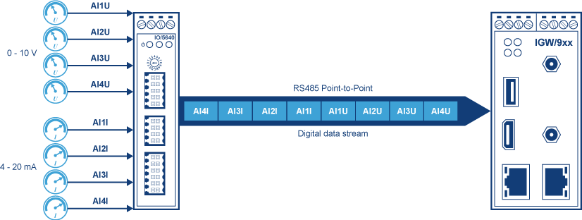
Figure 4: RS485 Point-to-Point with data stream
| Number of channels | Max. sample frequency | Sample interval |
|---|---|---|
| 1 | 2300 Hz | 434 µsec |
| 2 | 1645 Hz | 607 µsec |
| 3 | 1280 Hz | 781 µsec |
| 4 | 1047 Hz | 955 µsec |
| 5 | 886 Hz | 1.12 msec |
| 6 | 768 Hz | 1.3 msec |
| 7 | 677 Hz | 1.47 msec |
| 8 | 606 Hz | 1.65 msec |
| Sampling rates depending on the number of channels | ||
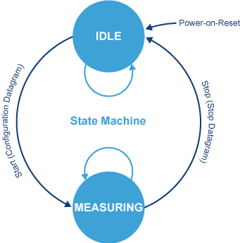
Figure 5: Scheme of the State Machine in the IO/5640-DS
To change from the MEASURING state back into the initial IDLE state and thus stop the transmission of further measurement data datagrams, a stop datagram must be sent to the IO/5640-DS.
As an accessory for the IO/5640-DS, PyDSlog, an open source Python library for recording arbitrary sensor readings in CSV files, is available. This library enables very fast raw sensor data acquisition via the analog inputs.
The CSV data can be used for exploratory or descriptive data analysis as well as for the training of machine learning algorithms for pattern recognition. Each individual measurement is saved as numeric value in a feature vector.
Such a vector (array of numeric values) represents the measured values of the entire IO/5640-DS input sensor system at a specific point in time.
In other words, the individual feature vector describes a time-specific state pattern of the respective sensor readings. The CSV file itself forms a data set of feature vectors that were recorded at different points in time.
In addition to the data from the eight analog channels, PyDSlog also allows the addition of other data such as a timestamp for Time Series CSV files and a machine learning label field to classify the state pattern of a feature vector.
The sensor measurement data collected via PyDSlog can be processed directly with other Python libraries.
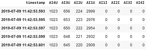
Figure 6: Example of a CSV file with measured values
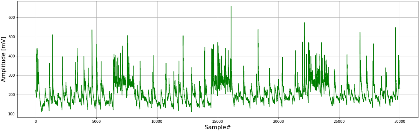
Figure 7: Visualization of measured data
Thus, a PyDSlog CSV file can be read into a NumPy array or a Pandas DataFrame without any further conversion or editing steps and, for example, be visualized with the aid of Matplotlib, as shown in figure 7.
The cables used for wiring the IO/5640 must include the following specifications:
The screwdriver used for the terminal strip must not be wider than 2.5 mm.
| Parameter | Property / Value |
|---|---|
| Number of inputs | 4 |
| Input voltage max. | ±17 V |
| Signal voltage | 0 .. 10 V |
| Input resistance | typ. 1 MΩ |
| Resolution | 12 Bit |
| Conversion time | typ. 10 ms |
| Measurement error at 25 °C | < ±0,2% from full scale value |
| Temperature coefficient 0 .. 70 °C | < ±0,0015%/K from full scale value |
This data format is only valid for the IO/5640 in Modbus operation.
| Input voltage (V) | Measurement Hex |
|---|---|
| < 0,0 | 0x7FFF |
| 0,0 | 0x0000 |
| 2,5 | 0x2000 |
| 5,0 | 0x4000 |
| 7,5 | 0x6000 |
| 10,0 | 0x7FF8 |
| > 10,0 | 0x7FF9 |
This data format is only valid for the IO/5640-DS in Data Stream operation.
For each selected channel 2 bytes are transmitted as Unsigned Int16 (16-bit integer) in Little Endian Mode with 12-bit ADC resolution.
Conversion of the 16-bit integer measurement values:
U(x) = x * 0,0025 V.
All signals refer to AIGND.
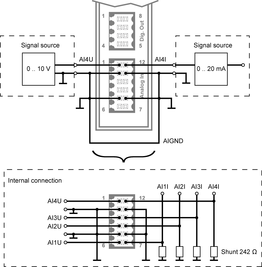
Figure 8: Connection scheme analog input
| Parameter | Property / Value |
|---|---|
| Number of inputs | 4 |
| Input voltage | ±10 V |
| Signal current | typ. 0 .. 20 mA |
| Input resistance | 242 Ω |
| Resolution | 12 Bit |
| Resolution | typ. 10 ms |
| Measurement error at 25 °C | < ±0,2% vom Skalenendwert |
| Temperature coefficient 0 .. 70 °C | < ±0,0025%/K from full scale value |
This data format is only valid for the IO/5640 in Modbus operation.
| Input current (mA) | Measurement Hex |
|---|---|
| < 0,0 | 0x7FFF |
| 0,0 | 0x0000 |
| 5,0 | 0x2000 |
| 10,0 | 0x4000 |
| 15,0 | 0x6000 |
| 20,0 | 0x7FF8 |
| > 20,0 | 0x7FF9 |
This data format is only valid for the IO/5640-DS in Data Stream operation.
For each selected channel 2 bytes are transmitted as Unsigned Int16 (16-bit integer) in Little Endian Mode with 12-bit ADC resolution.
Conversion of the 16-bit integer measurement values:
I(x) = x * (3125/620000) mA.
| Parameter | Property / Value |
|---|---|
| Number of inputs | 5 |
| Input voltage max. | ±50 V |
| H-Level | 18 .. 30 V |
| L-level | 0 .. 8 V |
| Input resistance | typ. 10 kΩ |
| Input current @ 24 V | typ. 2.3 mA |
| Input frequency max. | 1 kHz |
The digital input of the IO/5640 can be wired as a high side switch (fig. 9) or as a low side switch (fig. 10).
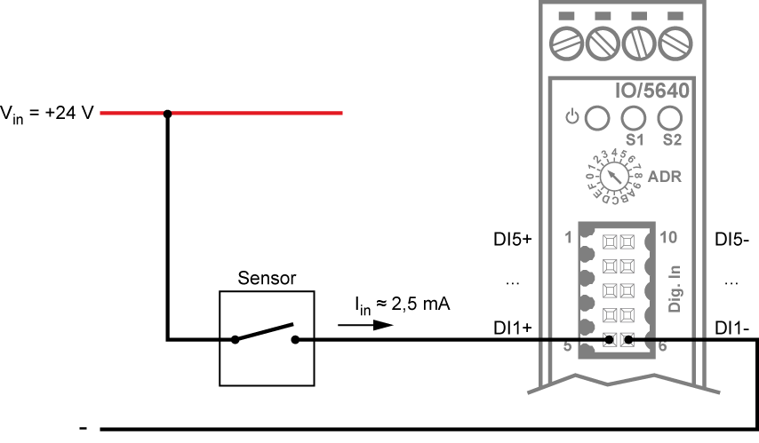
Figure 9: Connection scheme high side switch (PNP)
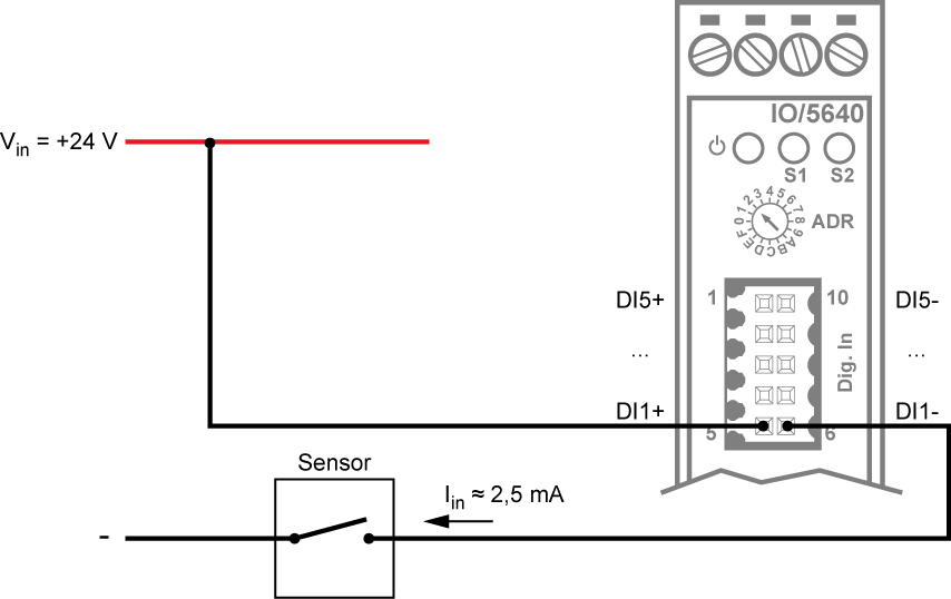
Figure 10: Connection scheme low side switch (NPN)
| Parameter | Property / Value |
|---|---|
| Number of outputs | 6 |
| Operating voltage (field side) | 24 VDC ±10% |
| Current consumption (field side) | 15 mA (module + load) |
| Load type | ohmic, inductive, capacitive |
| Switching frequency max. | 3 kHz |
| Output current max. | 0,5 A |
| Short-circuit current typ. | 1,1 A |
| ON resistance @ 0,5 A | 150 .. 320 mΩ |
| Absorbable energy W max. | 1 J; Lmax = 2 × Wmax / I2 |
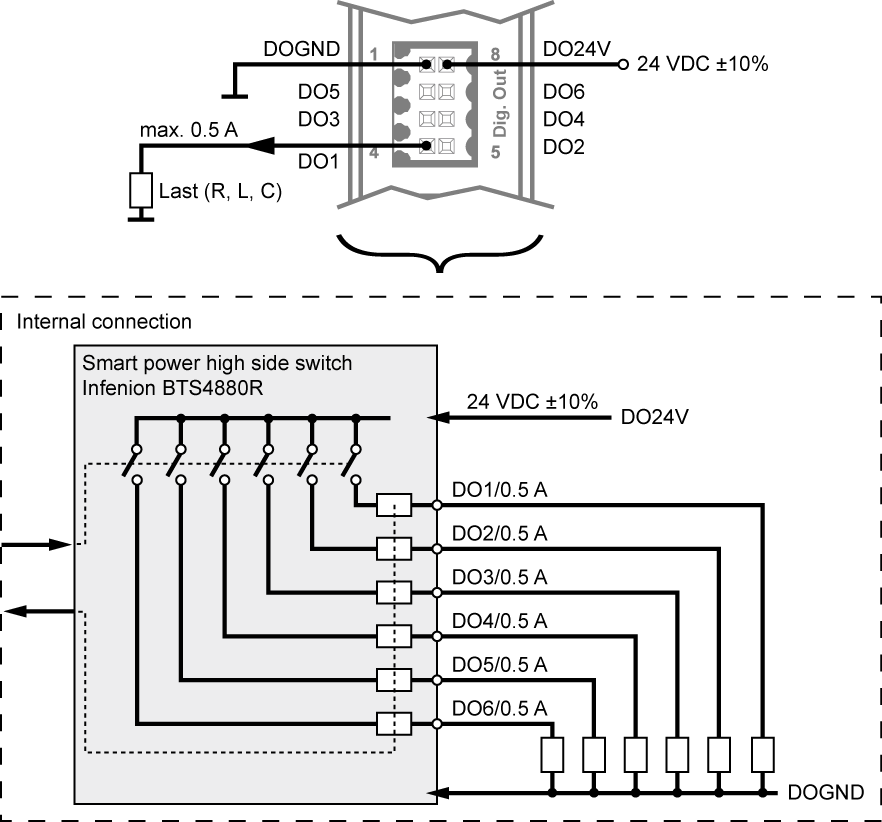
Figure 11: Connection scheme digital otput
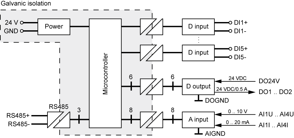
Figure 12: Potential separation
The IO/5640 is connected to the gateway/PC as a Modbus RTU slave via RS485 (half duplex). The slave address is set via the rotary switch on the front panel.
Address 15 is with termination. Adress 16 (position 0) is for service purposes only.
| Data type | Bits | Value range | Coding/byte order |
|---|---|---|---|
| UINT16 | 16 | 0 .. 216-1 | [DB1][DB0] (big endian) - High-Byte first |
| SINT16 | 16 | -32768 .. 32767 | [DB1][DB0] (big endian) - High-Byte first |
| UINT8 | 8 | 0 .. 255 |
| IO | Direction | Function | Register [dec] | Data type |
|---|---|---|---|---|
| DI1+/- | S > M S > M S > M |
FC2 FC3 FC3 |
0 8 [BIT0] 9 |
UINT8 UINT16 UINT16 |
| DI2+/- | S > M S > M S > M |
FC2 FC3 FC3 |
1 8 [BIT1] 10 |
UINT8 UINT16 UINT16 |
| DI3+/- | S > M S > M S > M |
FC2 FC3 FC3 |
2 8 [BIT2] 11 |
UINT8 UINT16 UINT16 |
| DI4+/- | S > M S > M S > M |
FC2 FC3 FC3 |
3 8 [BIT3] 12 |
UINT8 UINT16 UINT16 |
| DI5+/- | S > M S > M S > M |
FC2 FC3 FC3 |
4 8 [BIT4] 13 |
UINT8 UINT16 UINT16 |
| IO | Direction | Function | Register [dec] | Data type |
|---|---|---|---|---|
| DO1 | M > S S > M M > S S > M |
FC5 FC1 FC6 FC3 |
0 0 14 [BIT0] 14 [BIT0] |
UINT8 UINT8 UINT16 UINT16 |
| DO2 | M > S S > M M > S S > M |
FC5 FC1 FC6 FC3 |
1 1 14 [BIT1] 14 [BIT1] |
UINT8 UINT8 UINT16 UINT16 |
| DO3 | M > S S > M M > S S > M |
FC5 FC1 FC6 FC3 |
2 2 14 [BIT2] 14 [BIT2] |
UINT8 UINT8 UINT16 UINT16 |
| DO4 | M > S S > M M > S S > M |
FC5 FC1 FC6 FC3 |
3 3 14 [BIT3] 14 [BIT3] |
UINT8 UINT8 UINT16 UINT16 |
| DO5 | M > S S > M M > S S > M |
FC5 FC1 FC6 FC3 |
4 4 14 [BIT4] 14 [BIT4] |
UINT8 UINT8 UINT16 UINT16 |
| DO6 | M > S S > M M > S S > M |
FC5 FC1 FC6 FC3 |
5 5 14 [BIT5] 14 [BIT5] |
UINT8 UINT8 UINT16 UINT16 |
| DO1 .. 6 | S > M |
FC3 |
15 [BIT0] 15 [BIT1] |
UINT16 |
| IO | Direction | Function | Register [dec] | Data type |
|---|---|---|---|---|
| AI1U | S > M | FC3 | 16 | SINT16 |
| AI2U | S > M | FC3 | 17 | SINT16 |
| AI3U | S > M | FC3 | 18 | SINT16 |
| AI4U | S > M | FC3 | 19 | SINT16 |
| AI1I | S > M | FC3 | 20 | SINT16 |
| AI2I | S > M | FC3 | 21 | SINT16 |
| AI3I | S > M | FC3 | 22 | SINT16 |
| AI4I | S > M | FC3 | 23 | SINT16 |
| IO | Direction | Function | Reg. [dec] | Data type |
|---|---|---|---|---|
| LED_S1 | M > S S > M |
FC6 FC3 |
25 25 |
UINT16 UINT16 |
| LED_S2 | M > S S > M |
FC6 FC3 |
26 26 |
UINT16 UINT16 |
| DT1 | S > M | FC3 | 54 | UINT16 |
| DT2 | S > M | FC3 | 55 | UINT16 |
| SW_SVN | S > M | FC3 | 0 | UINT16 |
| SW_BUILD | S > M | FC3 | 1 | UINT16 |
| SW_VERSION | S > M | FC3 | 2 | UINT16 |
| DEVICE_NAME | S > M S > M S > M S > M |
FC3 FC3 FC3 FC3 |
3 4 5 6 |
UINT16 UINT16 UINT16 UINT16 |
| WATCHDOG | M > S S > M |
FC6 FC3 |
7 7 |
UINT16 UINT16 |
| Name | Description |
|---|---|
| IO/5640 | 6 digital outputs, 5 digital and 8 analog inputs, operation as Modbus RTU slave |
| IO/5640-DS | 8 analog inputs for data acquisition in Data Stream Mode, PyDSlog library for data recording in CSV files |
| USB Adapter | RS485 to USB adapter with 2 m cable length for connecting the IO/5640(-DS) to a PC |
SSV SOFTWARE SYSTEMS
Dünenweg 5
30419 Hannover
Phone: +49(0)511 · 40 000-0
Fax: +49(0)511 · 40 000-40
© 2026 SSV SOFTWARE SYSTEMS GmbH // All rights reserved.
ISO 9001:2015